M50-3111042
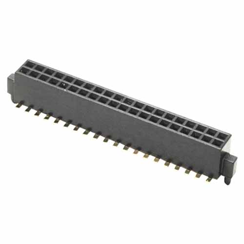
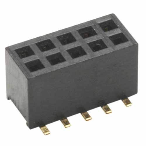
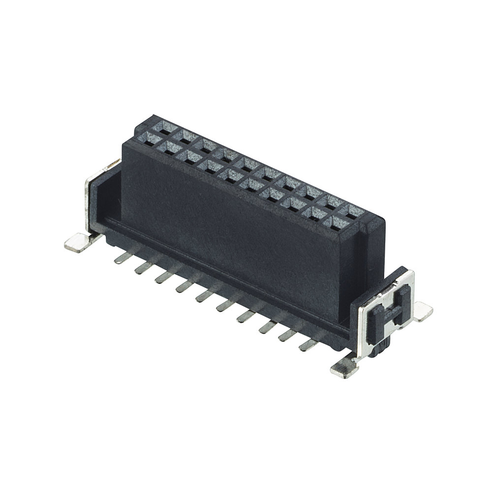
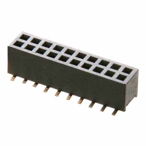
10+10 Pos. Female DIL Vertical SMT Conn.
1.27mm (0.05") Pitch PCB Connector - Archer M50 Board-To-Board
Loading… Check availability
10 similar products View products
Traceparts account required
Product Description
- Double Row Surface Mount, Dual (Top and Bottom) Entry with location pegs, 3.6mm connector height – 20 contacts (10+10).
- Gold finish on contact area, Tin finish on termination.
- Packaged in tubes.
Traceparts account required
Technical Details
Specification
EU RoHS Status:
Contact Pitch:
1.27mm (0.05")
Contact Gender:
Female/Socket/Jack
Connector Orientation:
Vertical
Connection Type:
Surface Mount (SMT)
Mating Pin Size:
0.4mm square
Current Rating:
1A per contact
Operating Temperature:
-40°C to +105°C
Soldering Data:
Max Solder Temperature: 260°C for 10 seconds
Polarising Features:
No
End Stackable:
No
Side Stackable:
No
Can be cut to another size:
No
Number of Rows:
2
Number of Signal Contacts:
20
Entry Style:
Dual Entry (Bottom Entry, Top Entry)
Materials
Finish / Plating on Termination:
100% Tin over Nickel
Finish / Plating on Contact Surface:
Gold
Base Material of Contact:
Phosphor Bronze
Housing Material:
Polyamide (Nylon) 9T
Housing Colour:
Black
Housing Material UL Rating:
UL94V-0
Packaging Style:
Tube
Dimensions
Individual Part Weight:
0.385g
Overall Dimensions (L x W x D) in mm:
15.80 x 4.60 x 5.50
Height of Connector above PCB:
4.60mm
Mating Profiles:
Frequently Asked Questions Ask a Question
Can the location pegs be soldered to the PCB?
No, the location pegs are part of the plastic housing and are therefore not suitable for soldering to the PCB. Only the SMT tails can be soldered – the location pegs are purely to assist with location, not board retention.
Was this answer useful?
Can cable assembly M50-9021042 be used alongside this connector and have M50-3651042R on the other end of FRC cable?
The female end of M50-9021042 will mate with the male PCB connector M50-3651042R. You would need to use a different connector from the M50 series to mate with the male connection on the end of the M50-9021042, or solder the male end directly to a PCB. The M50-3111042 should be suitable, but please note we have not specifically tested this connection. If you need further assistance, do please contact one of our Experts.
Was this answer useful?
Can I know the pin numbering for this connector?
For this range, we do not specify any particular pin numbering system. You are free to use any convention you prefer, or use your own. There is no marking on the product to indicate a number 1 pin. You can also find information on pin numbering on our Support article on this topic.
Was this answer useful?
Why does the recommended PCB layout have relief holes under each socket location when it is an SMT connector?
These “relief” holes are for the mating male pins – either for when it is used for bottom entry, or if the male pins used are longer than the height of the connector. If neither of these situations apply to your application, then you do not need the holes under each socket in your PCB design. You will only need the two holes for the location pegs.
Was this answer useful?
Downloads
TECHNICAL DOCUMENTS
INSTRUCTION SHEETS
OTHER DOWNLOADS
How can we help you?
If you would like to talk to someone about Harwin’s product, technical knowledge or documentation, contact one of our Experts for assistance.
ECAD Download Options
These ECAD files are provided by TraceParts
Register now or enter your registered email below
Uh oh, it looks like you are using an outdated browser version.
Some functions may not work as expected on Harwin.com in your current browser. For the best experience, more security and speed, we recommend updating your browser to the latest version.
(if you are using Internet Explorer, we recommend switching to an alternative browser.)
Still having issue? Contact [email protected] for help.
