
Flex Circuit or Cable?
 Written by
Wendy Jane
Preston
Written by
Wendy Jane
Preston
When you need to transfer signal current from one PCB to another, there is a choice of different methods to make the connection. In many instances the two boards cannot be connected directly but need a linking method. Understanding the advantages and restrictions of the different methods will help you achieve the correct choice for your build.

In this article we cover the main differences between flex printed circuit connections and cable connections. These two options are a good choice for using with high-reliability connectors, to resist extreme environments. There are other choices that might work in commercial or cost-first designs in applicable markets, but for now we will compare just two options.
Download this article in PDF format
Characteristics of a Flex Circuit connection
Flex circuit assemblies are manufactured from a combination of rigid PCBs (under the connectors) leading into the flexible connection section. The metal tracks are sandwiched inside a protective encapsulation, which insulates them and keeps them separate but held in place. The metal tracks are a thin rectangular cross-section, allowing this section of the assembly to be very flexible.

Connectors can be either SMT soldered or through-hole soldered, normally with shorter tails than intended for standard PCBs. This connection type has been common in high-density consumer electronics for many years (cell phones, laptops, flat-screen TVs), but the drive to minimize the size of electronics in all applications is making the use of FPC more widespread.
Download our Flex Circuit Assemblies PTM
Characteristics of an Equipment Cable connection
Cable assemblies can use a variety of different equipment wires to connect one cable connector to another. Ideally, connectors designed for cables should be used, but in rare circumstances (such as prototyping) it’s possible to use a throughboard connector and solder a wire to each termination.
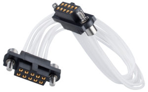
Cables are constructed from a solid core or stranded conductor, and then each core is insulated separately. Completed cable bundles can then have cable ties, heatshrink or an outer braid added to keep the cables together during assembly to the rest of the system, and often through the life of the product.
Flex and cable comparisons
Let’s look at each of the main differences to help you make your best choice.
Flexibility of connection – Cable
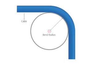
Cable is a great connection method that has been popular for many years. Most signal wires will be coated with flexible insulation such as PTFE, PVC or Silicone. If you have multiple bends to make in different directions, it’s the right choice. Watch out for:
- Bend radius – allow 6 to 10 times the insulation diameter for each cable.
- Dynamic bends – if you have a bend that will be moved many times during the life of the product. The materials become work-hardened and eventually brittle.
Flexibility of connection – FPC
Flexible Printed Circuit (FPC) has a bend radius which, at first glance, seems worse – 10 times the thickness for a static bend, 20 times for a dynamic bend. However, the thickness of an FPC is far thinner – potentially 0.185mm instead of 0.6mm. This gives you a resultant bend smaller than cables.
In addition, flex circuit can handle dynamic bending from thousands to millions of cycles, depending on the materials, frequency, bend radius and other factors.
The main downside is making sure your bend is placed across the direction of the FPC. If you need to incorporate twists or multiple direction changes then either a customized flex assembly is necessary, or cables are the better choice.
Weight
It’s a simple comparison – cables use solid or stranded cores where the metal is in a cylinder shape. The tracks in an FPC are very thin rectangles in cross-section, using much less material, and therefore FPCs will generally weigh less. This has an impact on the next characteristic and it’s important to understand which factor is more crucial for your design.
Current Rating
The lower amount of metal in the track compared to a cable connection does mean that the current rating per track is also likely to be lower. Make sure you understand your current requirements – flex should still be suitable for most data requirements.
Space Envelope
The space required for a PCB-to-cable connection includes two factors. Firstly, the height of the cable connector itself is higher than the equivalent board-mounting connector. Secondly, cables leaving the back of the connection vertically need space to allow for the bend radius. It may even be necessary to add padding on the opposite device, board or enclosure, to ensure the bent cable does not wear during life in the field.
With the FPC leaving the SMT connector at right angles, both aspects of this connection height are eliminated.

Materials & Environmental Factors
Connectors, cables, FPCs and accessories are all available in a variety of materials. Establish your temperature requirements in operation early on, and check that all material choices in your cable or FPC connection will withstand the operating range. Is outgassing also a factor for your application? Perhaps contamination by oils, fuels and other chemicals, or fungal growth? What about electromagnetic or radio frequency interference (EMI/RFI)?
If you have any environmental concerns that affect material choice, work with your supplier to check your end product is suitable for all the factors involved. If your environment is too aggressive, maybe protection methods will be needed. For EMI, external braiding may be possible on a cable bundle, but flex connections may be less prone to EM emissions. Testing may be necessary to confirm the best choice in any specific application.
How can Harwin help?
With the addition of Flex Circuit Assemblies added to the Harwin range of high-reliability connections, we can now help you in an even wider range of applications. With both the fully assembled Cable Assemblies and the Flex Assemblies, no tooling or production is required.
We’re happy to go through your design criteria, and help you choose the best connection method for your needs. Let us know if weight, space, or current rating are your important factors, and the route your connection will follow. We’ll go through all your options and make sure you can be confident with your connection choice.
How can we help you?
Our Experts are happy and willing to advise how to choose Harwin products in your challenging environment and application.
More articles for you


What is Hi-Rel or High-Reliability for connectors?
23 April 2020
The Demands of the Medical Equipment Market
15 April 2020Uh oh, it looks like you are using an outdated browser version.
Some functions may not work as expected on Harwin.com in your current browser. For the best experience, more security and speed, we recommend updating your browser to the latest version.
(if you are using Internet Explorer, we recommend switching to an alternative browser.)
Still having issue? Contact [email protected] for help.