M80-5410405
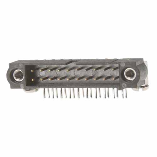
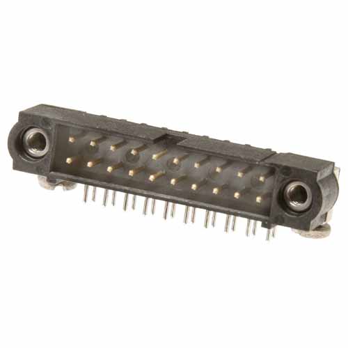
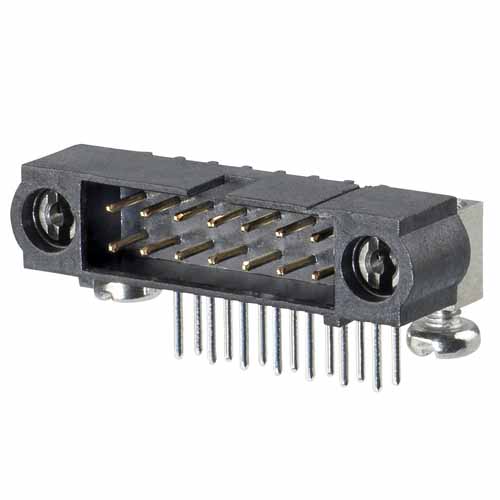
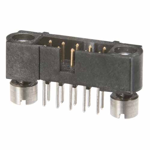
2+2 Pos. Male DIL Horizontal Throughboard Conn. Jackscrews
2.00mm Pitch High-Reliability Connector - Datamate J-Tek
Loading… Check availability
7 similar products View products
Traceparts account required
Product Description
- Double Row, 4.5mm PC Tail connector with 5mm board mount jackscrews – 4 contacts (2+2).
- Gold finish on contact area and termination. Slotted bolts provided for assembly to panel mount jackscrew. For spare board mount bolts, order M80-2270000B.
- For complete pin numbering or pin out information, see Component Specification C005XX.
Traceparts account required
Technical Details
Specification
EU RoHS Status:
Contact Pitch:
2.00mm (0.079")
Contact Gender:
Male/Plug
Connector Orientation:
Horizontal
Connection Type:
PC Tail / Throughboard
Mating Pin Size:
Ø0.5mm
Current Rating:
Dependent on mating contact
Operating Temperature:
-55°C to +125°C
Soldering Data:
Max Solder Temperature: 260°C for 10 seconds
Style of Jackscrews:
Internal Thread Jackscrew with Slotted Board Mount Bolts (Standard Gender)
Polarising Features:
Yes
End Stackable:
No
Side Stackable:
No
Can be cut to another size:
No
Number of Rows:
2
Number of Signal Contacts:
4
Materials
Finish / Plating on Termination:
Gold
Finish / Plating on Contact Surface:
Gold
Base Material of Contact:
Phosphor Bronze
Housing Material:
PPS
Housing Colour:
Black
Housing Material UL Rating:
UL94V-0
Packaging Style:
Tube
Dimensions
Individual Part Weight:
1.822g
Overall Dimensions (L x W x D) in mm:
14.00 x 8.60 x 10.50
Thread Size:
M2
Height of Connector above PCB:
6.00mm
Length of Throughboard Tail:
4.50mm
Mating Profiles:
Frequently Asked Questions Ask a Question
Are the board/panel mount bolts supplied with this connector, or do I have to order them separately?
Yes, these connectors are supplied with the board/panel mount bolts – they will come packaged in a separate bag. If you need some spares, you can use part number M80-2270000B to order more.
Was this answer useful?
I see a 0.1mm offset between the jackscrew and the center of the throughboard tails, but your footprint has the jackscrew hole central to the throughboard tails?
When the connectors are modeled on exact nominal dimensions, there is indeed a 0.1mm difference between the axis of the jackscrew and the central axis of the throughboard signal tails. This is visible and measurable on the CAD model. However, there is more than 0.1mm of float in the jackscrew and tail holes. Due to the bent nature of the tails, they tend to reduce this 0.1mm (within the allowed tolerances) in practice. We have produced boards ourselves with the centrally aligned layout, and not encountered any issues in assembling the connectors to the PCB. We also have multiple customers using these connectors that have not had any issues.
If you prefer to include the 0.1mm offset in your PCB layout, that is your choice – we supply the PCB footprints as guidelines and recommendations, and you are free to modify for your own processes and builds.
Was this answer useful?
What torque value should be used for these jackscrews?
The torque value for board or panel mounting is 21±2cmN. The torque value for mating jackscrews is 23cmN max. Both values are given in the Component Specification C005xx (page 14).
Was this answer useful?
Downloads
TECHNICAL DOCUMENTS
TEST REPORTS
INSTRUCTION SHEETS
OTHER DOWNLOADS
How can we help you?
If you would like to talk to someone about Harwin’s product, technical knowledge or documentation, contact one of our Experts for assistance.
ECAD Download Options
These ECAD files are provided by TraceParts
Register now or enter your registered email below
Uh oh, it looks like you are using an outdated browser version.
Some functions may not work as expected on Harwin.com in your current browser. For the best experience, more security and speed, we recommend updating your browser to the latest version.
(if you are using Internet Explorer, we recommend switching to an alternative browser.)
Still having issue? Contact [email protected] for help.


