
Selecting the Best Connector Termination Method
 Written by
Wendy Jane
Preston
Written by
Wendy Jane
Preston
Board-to-board and cable-to-board connections rely on at least one half of the mating pair being electrically attached to a PCB. When choosing the right assembly method for your product, what should you consider?
Download this article in PDF format
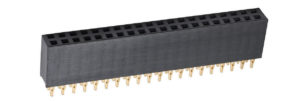
Through-Hole Technology (THT) and Wave Soldering
Wave soldering is tried and tested, and machines and methodology are well-established. The technique is an automated version of hand-soldering, using a standing wave to deliver solder to the underside of a PCB. The terminations (or tails) of the connector are sitting in (and through) holes on the board, and the solder is visible on the underside of the board.
Inspection is generally easy – the solder joints are not hidden, and inspection can be done by eye or with simple vision systems. Repairs or rework can be done using hand-soldering. Using through-hole components is also easier for prototyping, with easier soldering and rework giving greater scope for experimentation. The final design can still use the same throughboard connectors in volume production, removing any re-qualification requirements.
Because the tails sit through the board, this gives additional strength to the assembly, especially to lateral forces. This gives you very dependable strong joints, making it a favorite in avionics, military, space and other safety- or mission-critical applications.
The main disadvantage to THT is when products are being placed on the PCB. Not many of these connectors will be supplied in a suitable style for automation, with pick and place caps or tape packaging. This then requires a bank of production staff to hand-assemble components to the PCB, ready for feeding into the soldering process.
The wave soldering process itself also has a disadvantage – the process is obviously one-sided. Although more advanced techniques have been developed for PCBs with components on both sides, these will be much more costly than moving away from throughboard to another soldering technology.
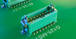
Pin-In-Paste (PIP) or Through-Hole Reflow (THR)
Pin-in-paste is a ‘bridging’ technology between Through-Hole and Surface Mount. Solder paste is printed into the throughboard holes, and then your terminations are pushed into and through this paste. This has the double benefits of the solder being pre-applied (like Surface Mount), and the stronger joints of Through-Hole. The soldering process is similar to Surface Mount, but process settings are more critical – otherwise your solder runs out your holes and into the bottom of your solder oven!
It’s also important to check that the components are suitable for PIP or THR. On wave soldering, the component is more protected from the direct heat off the solder wave, and plastics with a lower melting point can be used. In a reflow oven, the whole connector is exposed to the full solder temperature, and you need to make sure it can take the heat.
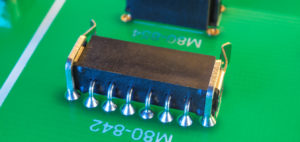
Surface Mount Technology (SMT)
Using this method, the connectors are placed onto the surface of the board, using flattened-out terminations laying on solder pad locations. Often these devices will be supplied in a package style suited for automated pick and place, greatly increasing the assembly throughput. The initial outlay in additional automated equipment is quickly paid back in savings in time and personnel.
The solder and flux mixture are printed onto the PCBs, and the product then ‘sticks’ to the solder mixture – so double-sided mounting is now possible, all done by machine. This improves board space use, and more components can be designed onto a single PCB. The whole PCB is then exposed to a reflow oven (other variations are also available), and the oven heat activates the solder process.
Surface mount has become the board assembly method of choice for high-volume production – but for the small to medium builds, or high-reliability sectors, there are a few downsides which might make it the wrong choice. For extreme environments, lateral forces can sometimes make the product or the SMT pads peel away from the PCB, at a lower force than a THT version would withstand. SMT product can be more expensive, and not all board components come in SMT types, so you may still end up with a mixed-technology circuit board. As this is a design suited for high-volume production, low-volume runs could be very cost-inefficient, with set-ups times longer than the actual production run. Finally, inspection can be much more difficult, and may require X-ray or similar to see solder joints partially or wholly obscured by the component itself.
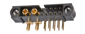
Press-Fit Terminations
Press-fit terminations are a much rarer method of assembly and are not available on many types of connector and other devices. The termination contains a compliant section, which is inserted into a plated-through hole on the PCB. The compliant section will collapse slightly, but still retain enough spring-force to maintain a gas-tight joint against the plated hole. The advantage is immediately obvious – no soldering is required, a single operation of inserting the connector has provided an electrical connection. The elimination of a heat cycle (during soldering) also protects heat-sensitive components from possible damage.
As the assembly method is a mechanical push, it is only suitable for more robust or larger components. The forces involved in getting all the terminations squeezed into the PCB holes are high and add up with more terminations. So, the component itself must be capable of taking the assembly ‘push’ without damage. The holes themselves need to be manufactured to a tighter tolerance than required for standard THT, increasing the board cost. Then there is simple availability – there may not even be an existing design!
Which Technology?
Although the last two decades has seen movement away from THT in some applications, there are still many valid uses for this method, most notably for reliability. But depending on product availability and volumes, SMT and Press-Fit all have their own uses, and are all now well-established.
Your decision on which technology to use will need to be chosen at the early stages of your concept design and will influence your choice of connectors and other devices. Make sure you have all the information you need and do some research into products available.
How can we help you?
If you would like to talk to someone about Harwin’s product, technical knowledge or documentation, contact one of our Experts for assistance.
More articles for you

Flex Circuit or Cable?
17 September 2020
5 Considerations for PCB Layouts
06 August 2020
What is Panel Mount?
09 April 2020Uh oh, it looks like you are using an outdated browser version.
Some functions may not work as expected on Harwin.com in your current browser. For the best experience, more security and speed, we recommend updating your browser to the latest version.
(if you are using Internet Explorer, we recommend switching to an alternative browser.)
Still having issue? Contact [email protected] for help.